
Funpack-5-1
Hi everyone, I'm 代码小A
I'm very honored to take part in the Funpack-5-1 activity hosted by EETree (电子森林)
Project Introduction:
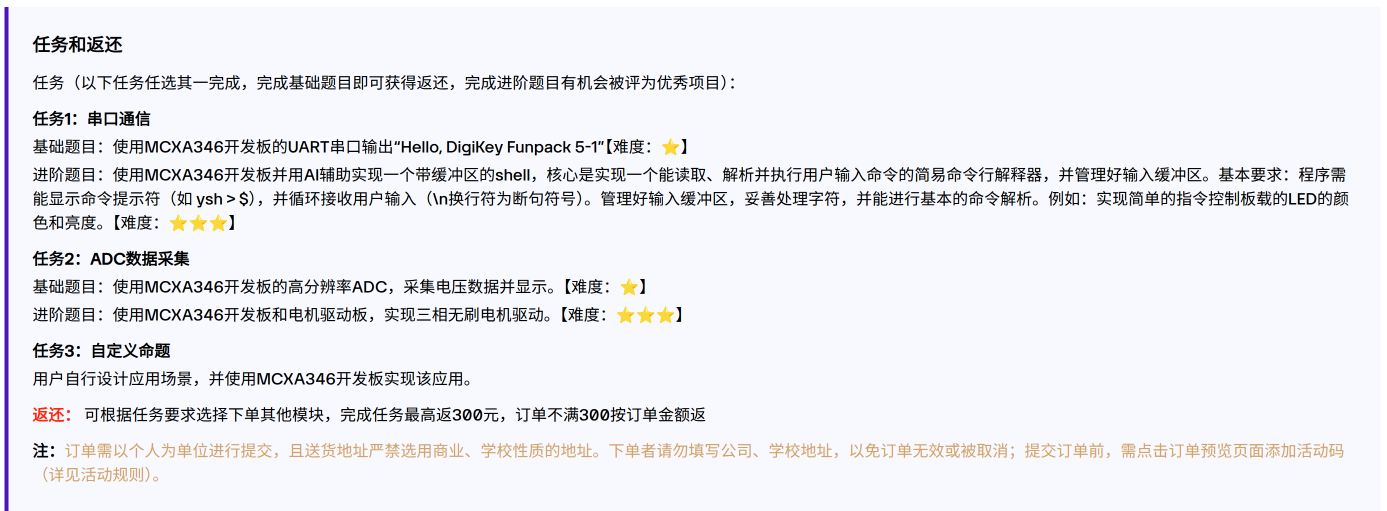
I've now completed both the basic and advanced challenges of Task 1, and picked up the basic challenge of Task 2 along the way
A Brief Introduction to All the Hardware Used
The hardware platform used is as follows: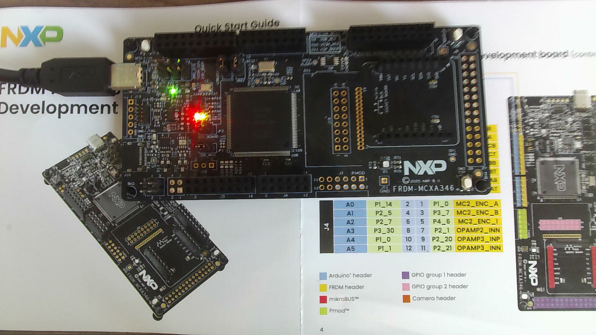
This development board is the NXP FRDM MCX A346 provided by EETree, with the following specs:
- MCX A346 with an Arm® Cortex®-M33 core running at up to 180MHz, 1MB flash, 256KB RAM, plus 8KB of error-correcting code (ECC) memory
- Dual FlexPWM, four 16-bit ADCs, a dedicated MAU math accelerator, and SmartDMA
- High-Speed USB (HS USB) Type-C connector (with an onboard MCU-Link debugger), and support for CAN/I3C/SPI/I²C/UART connectors (Arduino, PMOD/mikroBUS, DNP)
- Onboard MCU-Link debugger with CMSIS-DAP, JTAG/SWD connector
- Compatible with the Arduino, mikroBUS, and Pmod ecosystems
- Ideal for: industrial automation, motor control, and IoT edge computing
Peripherals Used
MCUXpresso IDE configuration view: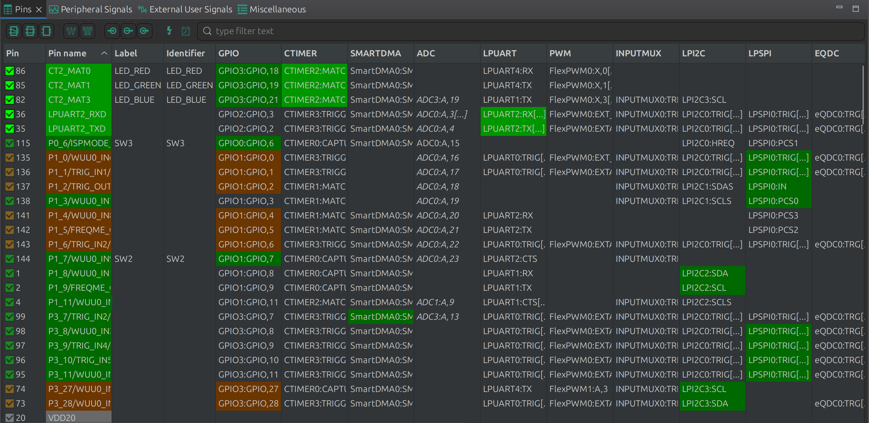
This project implements a feature-rich interactive Shell (OS-Less) on the NXP MCXA346 (FRDM-MCXA153) development board. The system mainly uses the following on-chip peripherals to implement its core functionality:
1. LPUART (Low-Power Universal Asynchronous Receiver/Transmitter)
- Purpose: command-line communication between the board and a PC (or the web dashboard).
- Feature usage:
- Non-blocking TX: data is sent using interrupts or DMA, paired with a custom
usart_printfunction, ensuring the main loop never locks up when printing large amounts of colored ASCII art and logs. - RingBuffer RX: uses
LPUART_TransferStartRingBufferto automatically stash received characters intog_rxRingBufferin the background, with the main loop polling them out efficiently. This lets the Shell fully support complex ANSI escape sequences (moving the cursor with the left/right arrow keys, paging through history with the up/down keys, etc.).
- Non-blocking TX: data is sent using interrupts or DMA, paired with a custom
2. CTIMER (Standard Counter/Timer)
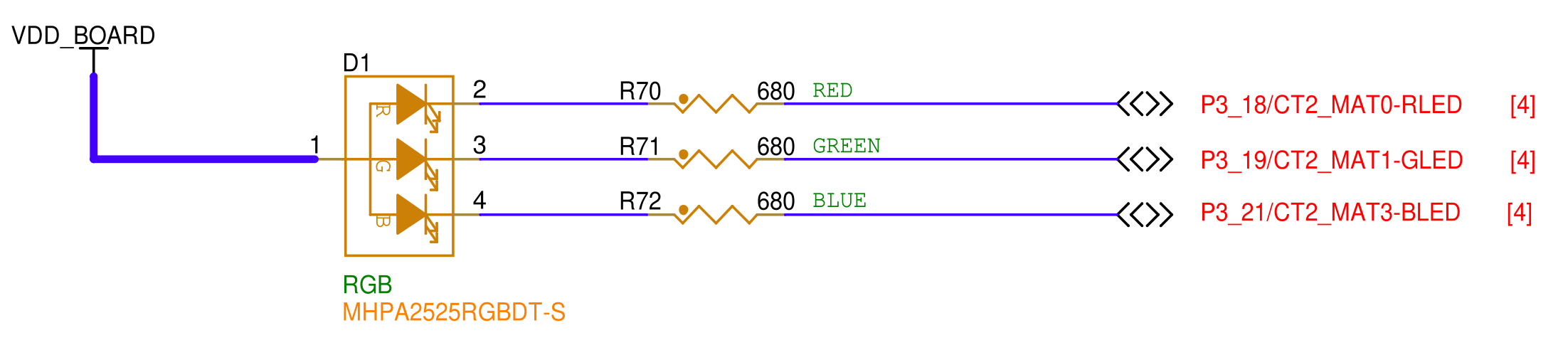
- Purpose: hardware-level stepless dimming of the RGB LED (PWM output).
- Feature usage:
- Multi-channel PWM: uses
CTIMER2(depending on the specific pin mapping). The Match 2 channel (CTIMER_MAT_PWM_PERIOD) is configured to produce a 20kHz base period. - Independent duty-cycle control: three separate channels —
CTIMER_MAT_OUT_RED(Match 0),CTIMER_MAT_OUT_GREEN(Match 1),CTIMER_MAT_OUT_BLUE(Match 3) — are mapped to the onboard R, G, and B LEDs respectively. Updating each channel's pulse width gives 0-255 levels of color adjustment.
- Multi-channel PWM: uses
3. LPADC (Low-Power Analog-to-Digital Converter)
- Purpose: read the chip's internal temperature sensor and extract the underlying analog voltage data.
- Feature usage:
- Internal channel multiplexing: connected to ADC channel 26 (
DEMO_LPADC_TEMP_SENS_CHANNEL), a hidden channel dedicated to measuring Core Temperature. - Hardware Averaging: configured for 128-sample hardware averaging (
kLPADC_HardwareAverageCount128), effectively filtering out electrical noise during high-speed operation. - Interrupts and calibration: automatic offset and gain calibration are enabled. It uses Software Trigger + interrupt service (
ADC0_IRQHandler). When reading the temperature, the dual-current method (obtaining and ) and the official non-linear compensation algorithm are used to calculate an accurate junction temperature.
- Internal channel multiplexing: connected to ADC channel 26 (
4. SysTick (System Tick Timer)
- Purpose: provide the system-level heartbeat used to update the software RTC (real-time clock).
- Feature usage:
- 1ms periodic interrupt: configured to fire 1000 times per second.
SysTick_Handlercounts them, and once the count reaches 1000 it triggers a one-second update, which in turn advances the customrtc_time_tstructure (year/month/day/hour/minute/second), giving the system a time base independent of the main loop.
- 1ms periodic interrupt: configured to fire 1000 times per second.
5. GPIO / Port Module (used indirectly)
- Purpose: physical mapping of peripheral pins.
- Feature usage: through the low-level
BOARD_InitHardware()(which usually includespin_mux.c), the UART signals are mapped to the pins of the USB-Serial bridge chip, and the CTIMER PWM signals are mapped to the pins driving the onboard RGB LED.
Block Diagram and Project Design Approach
Flow Diagram
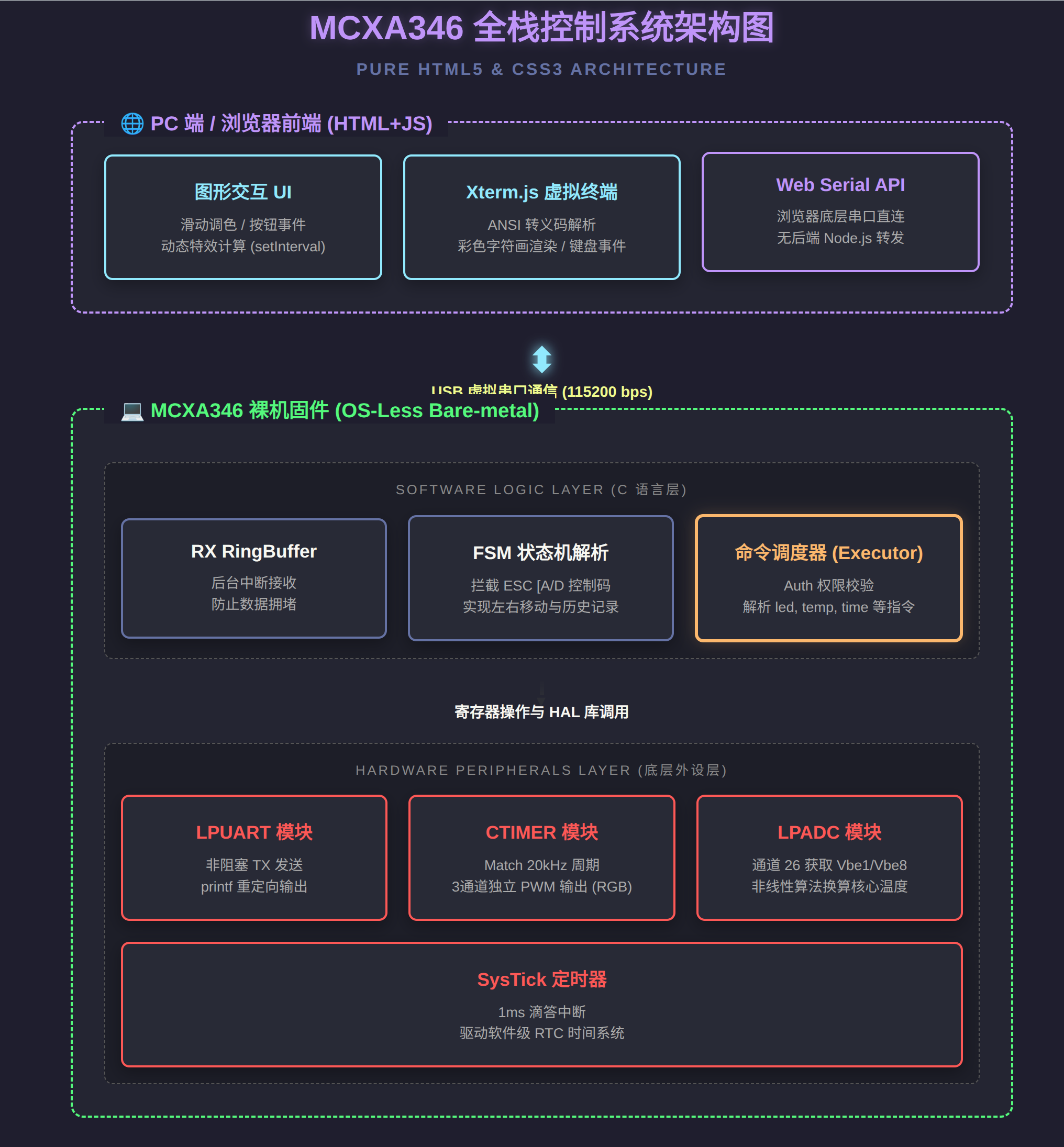
Design Approach and Key Code Walkthrough
Overall Flowchart
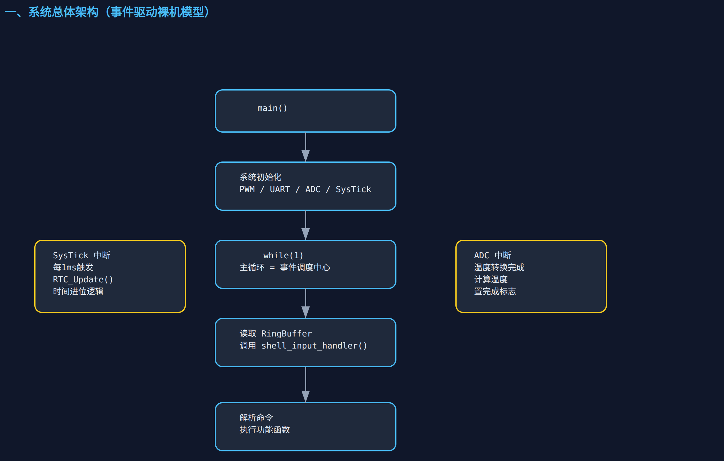
Shell Character Handling Flowchart
1. Low-Level Output Architecture: Variadic Parsing and "Semi-Asynchronous" Transmission
/* Custom Printf */
void usart_print(const char* format, ...) {
    static char print_buf[256];
    va_list arg;
    va_start(arg, format);
    int len = vsnprintf(print_buf, sizeof(print_buf), format, arg);
    va_end(arg);

    if (len > 0) {
        xfer_tx.data = (uint8_t*)print_buf;
        xfer_tx.dataSize = len;
        txOnGoing = true;
        LPUART_TransferSendNonBlocking(DEMO_LPUART, &g_lpuartHandle, &xfer_tx);
        while (txOnGoing); // Wait for the transmission to finish
    }
}
Explanation:
This is the output cornerstone of the entire Shell. To escape the heavy overhead of the standard-library printf and its potentially uncontrollable blocking, I hand-wrote a variadic print function.
- Variadic handling: using the
va_listmacros from<stdarg.h>together withvsnprintf, the formatted string (such as%d,%s) is safely packed intoprint_buf. - Transmission mechanism: this part is interesting. It calls NXP's fsl_lpuart non-blocking send function
LPUART_TransferSendNonBlocking, but the very next line spins inwhile (txOnGoing);. This effectively turns the asynchronous call into synchronous blocking. - Discussion: the upside of this approach is that the logic is dead simple, and buffer overwriting can never happen (say, the previous frame hasn't finished sending when the next frame flushes
print_buf). But it burns CPU time when printing at very high rates. If I later want pure asynchronous operation, I could introduce a transmit queue (Tx FIFO).
2. Core Peripheral Play: Temperature Calculation Based on Dual-Vbe Voltages
/* Official temperature measurement helper function */
float DEMO_MeasureTemperature(ADC_Type *base, uint32_t commandId, uint32_t index)
{
    // ... prior initialization omitted ...
    if (true == LPADC_GetConvResult(base, &convResultStruct))
    {
        Vbe1 = convResultStruct.convValue >> convResultShift;
        if (true == LPADC_GetConvResult(base, &convResultStruct))
        {
            Vbe8 = convResultStruct.convValue >> convResultShift;
            // Convert the raw ADC values into real voltages (assuming VDDA = 3.3V)
            g_Temp_Vbe1_Voltage = ((float)Vbe1 * 3.3f) / 65536.0f;
            g_Temp_Vbe8_Voltage = ((float)Vbe8 * 3.3f) / 65536.0f;

            temperature = parameterSlope * (parameterAlpha * ((float)Vbe8 - (float)Vbe1) /
                                            ((float)Vbe8 + parameterAlpha * ((float)Vbe8 - (float)Vbe1))) -
                          parameterOffset;
        }
    }
    return temperature;
}
Explanation:
This code shows the classic principle behind reading the internal temperature on the MCX family's LPADC. The temperature sensor inside an MCU usually doesn't output a voltage directly proportional to temperature; instead it exploits the temperature behavior of a transistor's base-emitter voltage (Vbe).
- Hardware principle: the chip injects and currents into the same PN junction, producing two different voltages,
Vbe1andVbe8. The difference between them () is strictly linear with absolute temperature. - Code implementation: the code reads two consecutive ADC conversion results (the ADC values under 1x and 8x current respectively). Here I also added a very intuitive physical-quantity mapping that converts the 16-bit (65536) ADC value back to a real analog value under the 3.3V reference. Finally the officially calibrated
parameterSlopeandparameterOffsetformula from NXP yields degrees Celsius.
3. The Soul of Interaction: A State Machine for VT100 Terminal Escape Sequences
/* Input Processor */
void shell_input_handler(uint8_t ch) {
    static int escState = 0;

    // ANSI Sequence Logic
    if (escState == 0 && ch == 0x1B) { escState = 1; return; }
    if (escState == 1) { escState = (ch == '[') ? 2 : 0; return; }
    if (escState == 2) {
        if (ch == 'A' || ch == 'B') {
            // ... handle the up/down arrow keys (history) ...
        }
        else if (ch == 'D') { // Left
            if (g_shellPos > 0) { g_shellPos--; usart_print("\b"); }
        }
        else if (ch == 'C') { // Right
            if (g_shellPos < g_shellLen) {
                char s[2] = {g_shellBuffer[g_shellPos], 0}; usart_print(s); g_shellPos++;
            }
        }
        escState = 0; return;
    }
    // ... handle enter, backspace, and regular characters ...
}
Explanation:
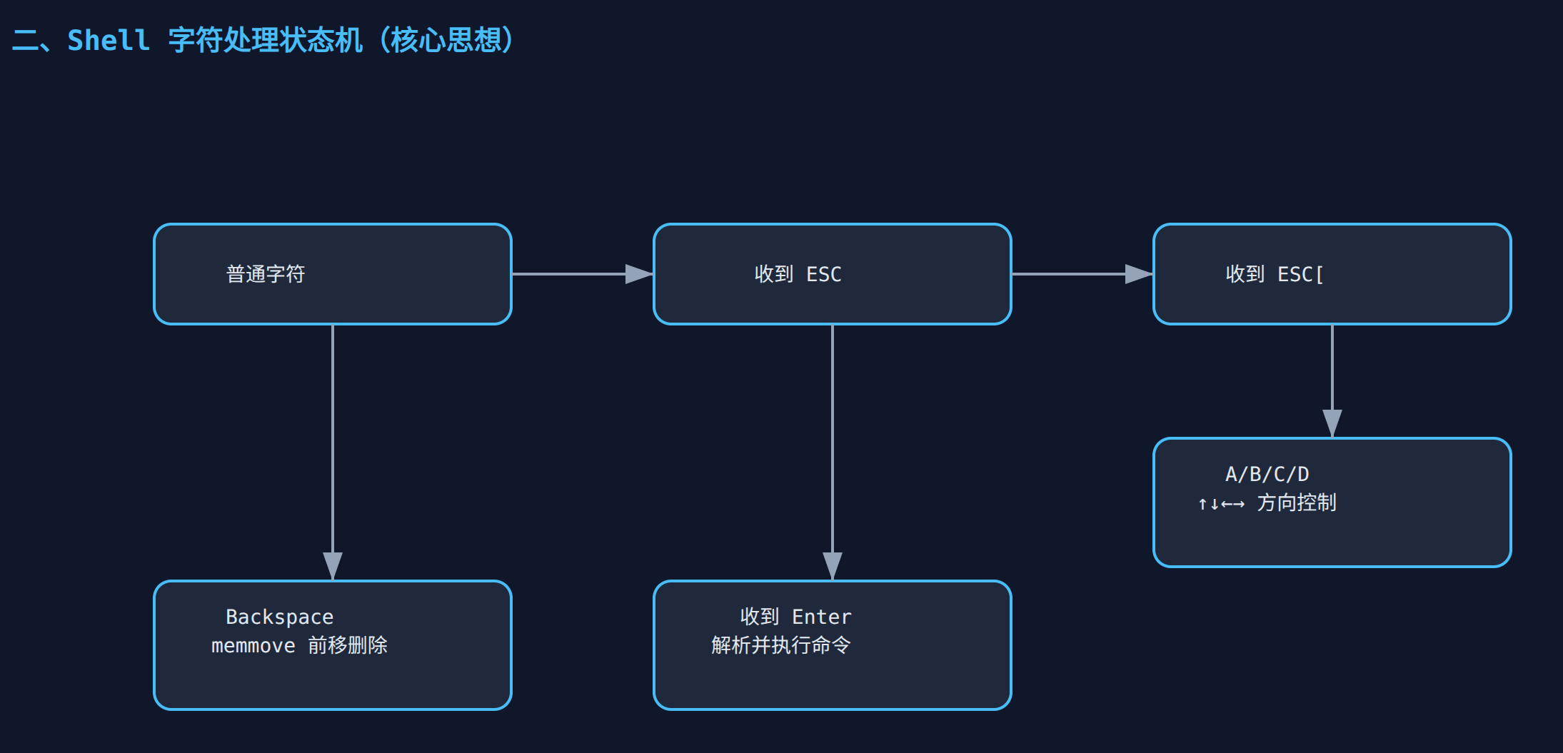
This is what gives this Shell its "modern" feel. When you press an arrow key (↑, ↓, ←, →), the serial port doesn't send a single character — it sends a 3-byte ANSI escape sequence (for example, the left arrow is 0x1B 0x5B 0x44, i.e. ESC [ D).
- State machine design: a remarkably neat lightweight state machine,
escState.- On
0x1B(ESC), enter state 1 and intercept the character without echoing it to the screen. - On
[, enter state 2, ready to receive a direction command. - On
A/B/C/D, run the corresponding cursor-movement or history-recall logic, then reset the state machine.
- On
- Cursor control: for instance, moving the cursor left (
ch == 'D') not only decrements the buffer cursorg_shellPos, but also sends\b(backspace) so the cursor on the terminal genuinely steps back one column. This hardware/software synchronization is really solid.
4. The Bare-Metal Scheduling Core: RingBuffer and Main-Loop Polling
int main(void) {
    // ... hardware, timer, and ADC initialization omitted ...

    // Start RingBuffer Background Receiving
    LPUART_TransferStartRingBuffer(DEMO_LPUART, &g_lpuartHandle, g_rxRingBuffer, RX_RING_BUFFER_SIZE);

    while (1) {
        size_t ringLen = LPUART_TransferGetRxRingBufferLength(DEMO_LPUART, &g_lpuartHandle);
        if (ringLen > 0) {
            size_t toRead = (ringLen > sizeof(g_tempRxBuffer)) ? sizeof(g_tempRxBuffer) : ringLen;
            rxXfer.data = g_tempRxBuffer;
            rxXfer.dataSize = toRead;

            // Pull data out of the RingBuffer into a temporary buffer
            LPUART_TransferReceiveNonBlocking(DEMO_LPUART, &g_lpuartHandle, &rxXfer, &receivedBytes);

            for (size_t i = 0; i < receivedBytes; i++) {
                shell_input_handler(g_tempRxBuffer[i]);
            }
        }
    }
}
Explanation:
In a system with no RTOS, how do you make sure data isn't lost when the user hammers the keyboard? The answer here is: low-level interrupt reception + upper-level polling.
- Decoupling mechanism:
LPUART_TransferStartRingBufferis a very handy API provided by NXP's HAL library. It enables the RX interrupt at the low level and quietly stuffs every received byte intog_rxRingBuffer. This process is purely hardware/interrupt driven and never disturbs the main loop for long. - Centralized processing: in the
while(1)loop, the system keeps checking whether the RingBuffer holds any unread data. If it does, it pulls it out in chunks (toRead) intog_tempRxBuffer, then feeds it byte by byte into the aforementionedshell_input_handlerstate machine. - Advantages: it strips the "time-consuming data parsing" out of the interrupt service routine (ISR), preserving the system's real-time behavior while also avoiding the overhead of frequent single-byte interrupt reads.
Debugging Software
The computer system used for development is Ubuntu24.04LTS
The development software used includes:
- MCUXpressoIDE: NXP's official development tool, used to write code, work with the SDK, and flash the program
- vscode: for editing code
- picocom: used to demonstrate the shell written for the MCU
The AI platforms used include Gemini, ChatGPT, Tongyi Qianwen
Feature Gallery and Notes
Power-On Printout
The operating system I use is Ubuntu24.04LTS
After opening the serial port with the command picocom -b 115200 /dev/ttyACM0 and pressing the reset button, the result is as follows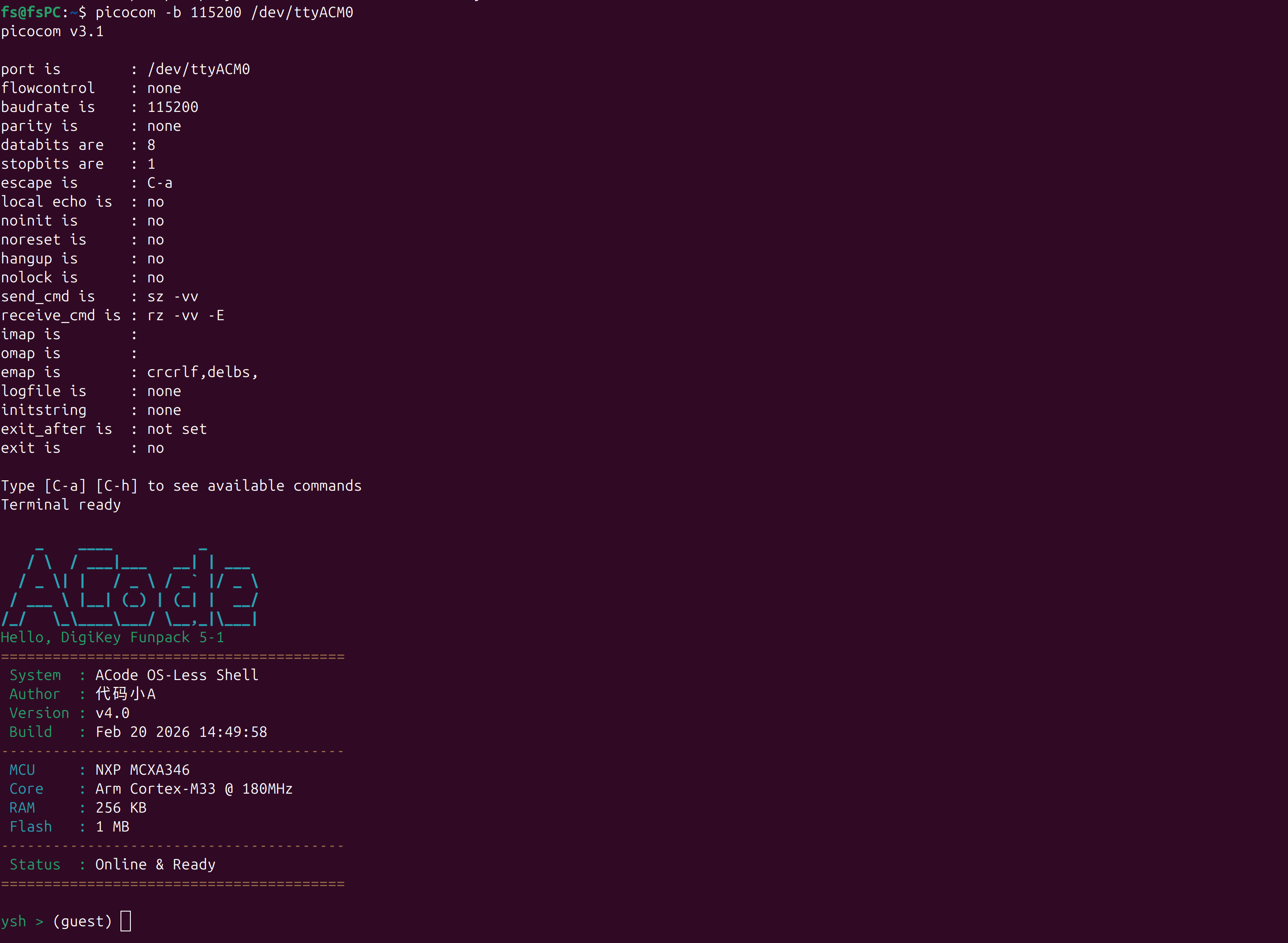
It prints, in order:
- LOGO: ACode and
- Hello, Digikey Funpack 5-1,
- Software-related information, such as name, author, version, and build time
- Hardware name, architecture, RAM, Flash
- The current status
- Finally it enters the shell; before logging in you're in guest mode and can't use all the commands, such as controlling the RGB
Command Usage
Use help to view all the commands available under your current privileges; use login adin 123456 to log in and gain access to all commands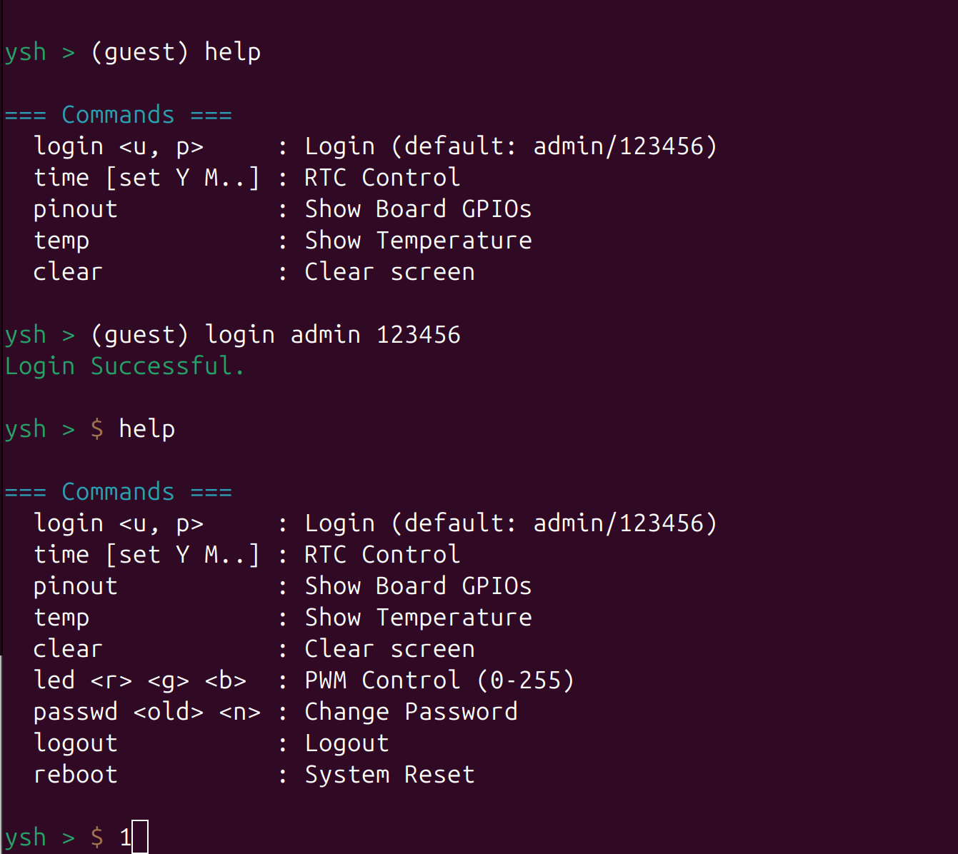
Use the time command to view the current system time, and time [set Y M..] to set the time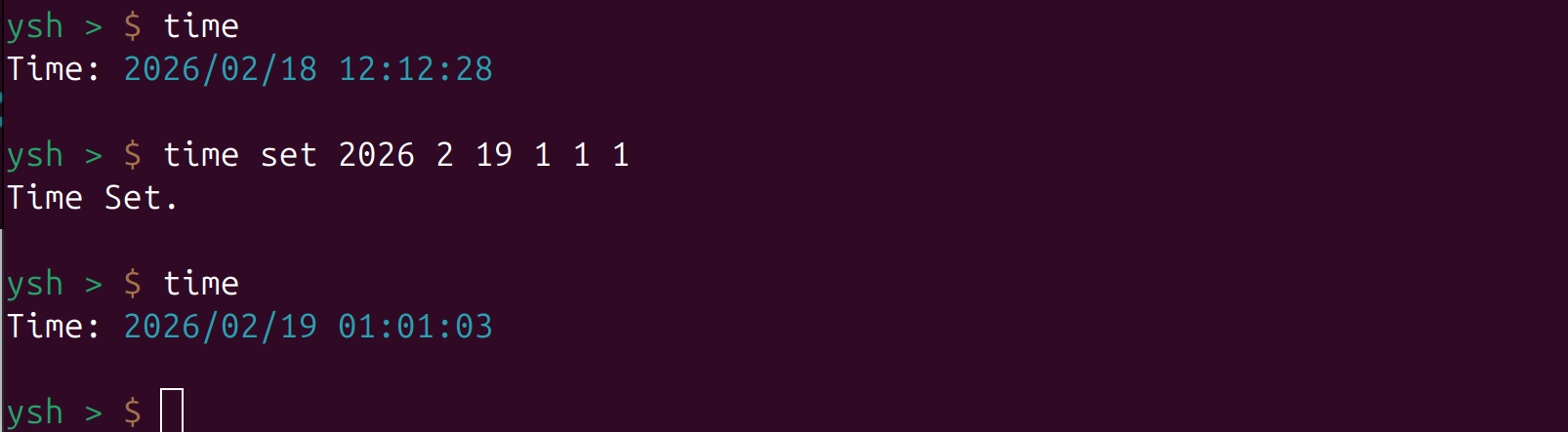
Use led r g b to change the RGB brightness
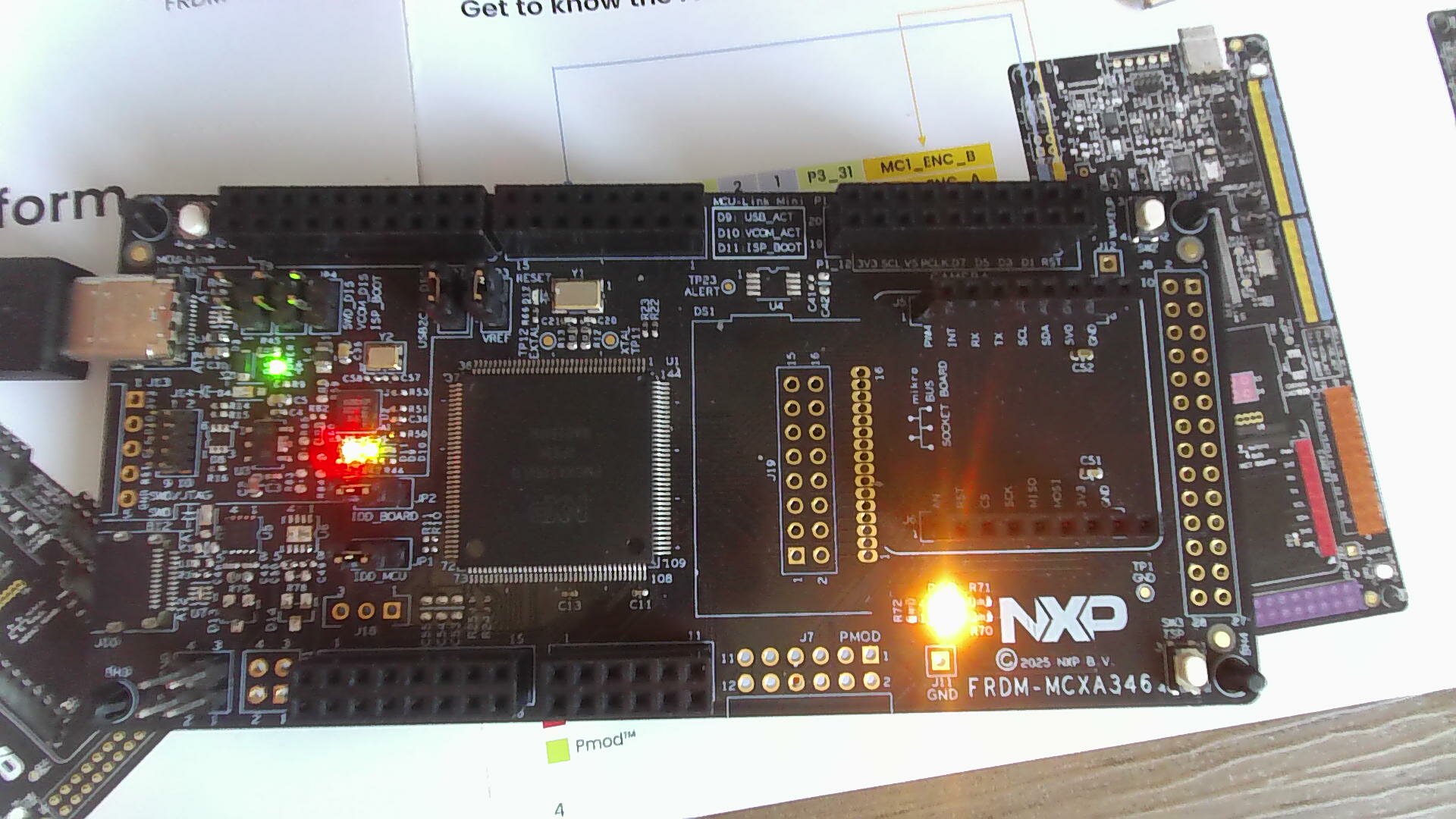
Use the command temp to view the chip temperature; it also shows the two voltages used to measure the temperature
Use the pinout command to view the board overview diagram and the pin details of J1, J2, J3, and J4 (inspired by the Raspberry Pi pinout command)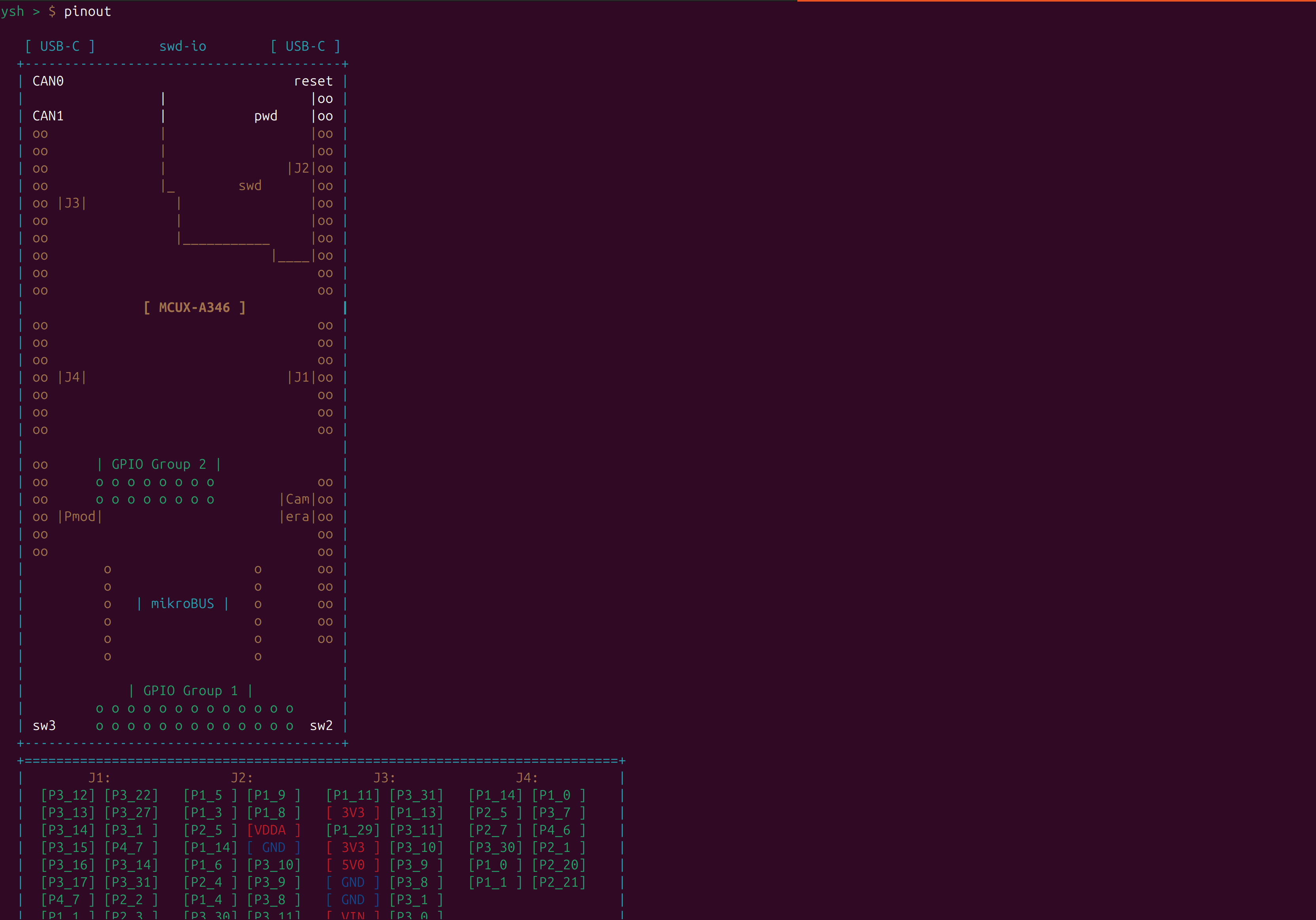
Web-Based Smart Terminal
This web terminal includes all the commands and lets you control peripherals by clicking or dragging; it also comes with several preset RGB display modes: blinking, breathing light, and rainbow breathing light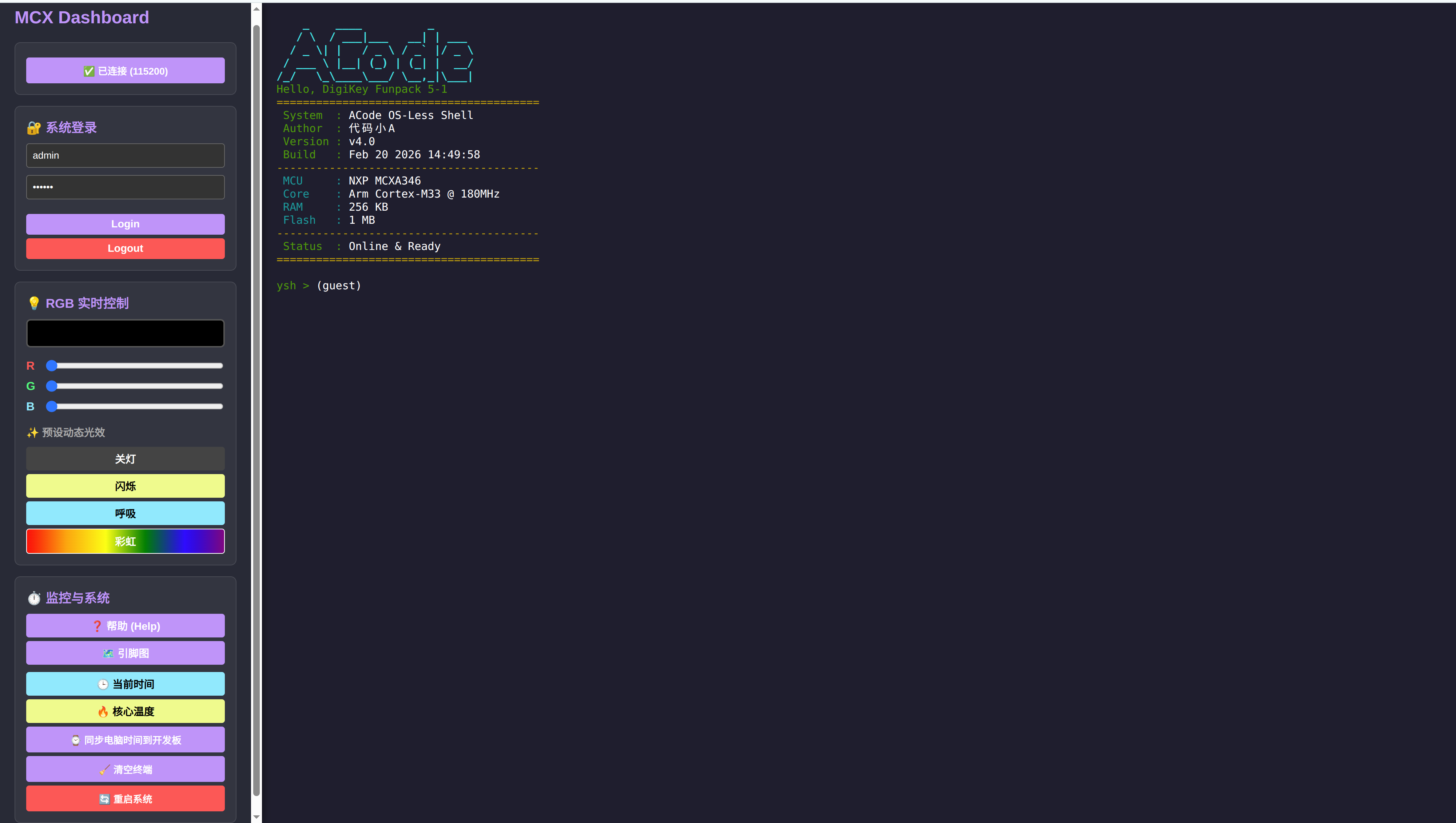
Problems Encountered in the Project and How I Solved Them
Problem 1: This was my first encounter with an NXP MCU, and the software has a bit of a learning curve — there are too few tutorials online!
Solution: Start by reading the getting-started documents published by EETree and NXP, get one example running, and then explore step by step. Try more! Try more! Try more!
Problem 2: The code was hard to understand, and I didn't know how to use the configuration tool to set up pins and so on
Solution: Run the official SDK first, modify from that base, read the code step by step, and ask AI whenever I don't understand something
Takeaways
Thanks to EETree for hosting this event, which gave me my first hands-on experience with an NXP-series MCU. This development board feels very finely designed, especially its dual-row header layout — "Arduino-compatible on the outside, all pins broken out on the inside". It not only has a great ecosystem, but also doesn't waste any of the IO resources of this powerful chip. The official MCUXpresso IDE is very pleasant to use as well; together with the graphical configuration tool, it saved me from a lot of hand-poking at low-level registers. Through this project, I've really got a feel for the ropes of NXP SDK development.
Besides the tooling experience, the code design this time was a real thrill. In the past, doing MCU work basically meant writing a while(1) loop, using delay for timing, and dumb-waiting for data in serial communication. But this time, to build an interactive Shell that "doesn't lock up", I forced myself to understand the concepts of ring buffers (RingBuffer) and state machines (FSM). The first time I pressed the up/down arrow keys in the serial terminal and scrolled back through history, and could move the cursor with the left/right keys to edit a command, that sense of accomplishment — "damn, I turned bare metal into Linux" — was truly beyond words.
Of course I hit quite a few potholes along the way, the deepest being reading the chip's internal temperature. At first I naively thought I could just copy the SDK code into my project — and ended up with an absurd temperature of -1300℃. Later, after studying the official SDK source in detail, it suddenly became clear: the MCU measures temperature internally using the physical mechanism of "two current sources producing a voltage difference" combined with interrupts, and there's even a complex non-linear compensation algorithm underneath. This made me fully appreciate why the vendor's BSP/HAL libraries exist — they elegantly wrap extremely complicated physical and analog behavior into interfaces we can call with ease.
Finally, pairing the MCU with a pure front-end web page (Web Serial API) was the "finishing touch" of this whole adventure. I used to think of hardware as nothing but dry black-box code; now I've found that as long as you open up your thinking, plain HTML and JS can give an MCU a cool host application — you don't even need to set up a backend server. Drag a slider and the RGB LED on the board changes color with no lag. That kind of full-stack development experience, from the front-end UI all the way down to the low-level hardware, is truly wonderful!
Overall, this time wasn't just about learning a new board; it also upgraded my embedded programming mindset from "single-track thinking" to the level of "event-driven and hardware/software decoupling". A huge gain, and I look forward to EETree cooking up even more fun projects in the future!
Changelog
0ca31-on