
BootLoader - Jump Only
Hardware:
- stm32f407 (JLC Sky Star)
- HC-05 Bluetooth module
Software: - Using Python for now as a crude demonstration of the functionality
Why Do We Need a Bootloader
- It's similar to a PC's boot: it lets us reinstall the system very conveniently — reinstall from a USB drive, reinstall online, and so on
- It lets you put fixed parameters into the bootloader, such as screen brightness, initial parameters, and so on, so you can focus on developing the APP
Prerequisites
Anatomy of a Microcontroller
Anatomy of a PC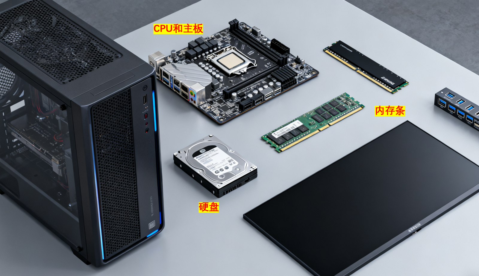
Inside the STM32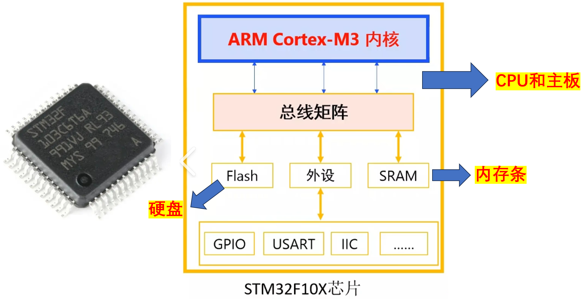
How the STM32 Boot Process Works
References:
- STM32F407 探索者开发指南V1.2.pdf
- STM32F4xx参考手册_V4(中文版).pdf
Where Flash and SRAM Live
Embedded SRAM is mapped at 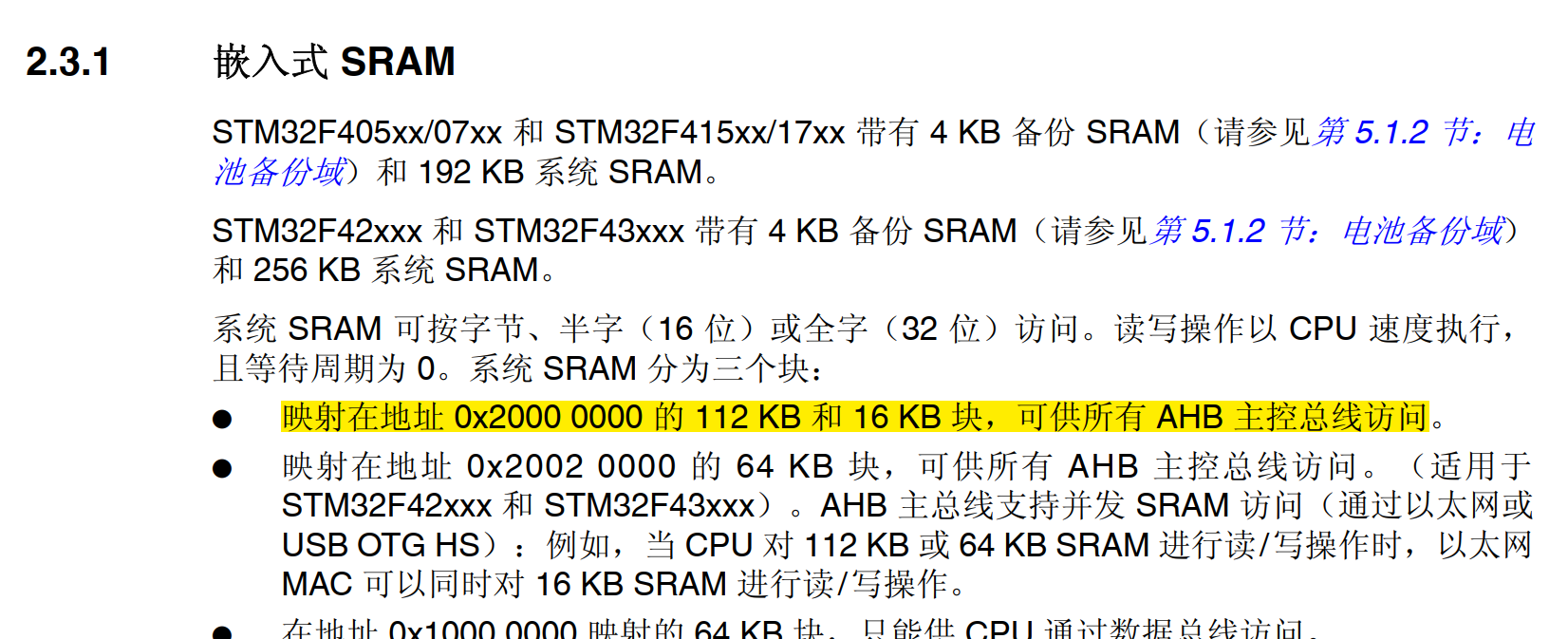
Embedded flash is mapped at 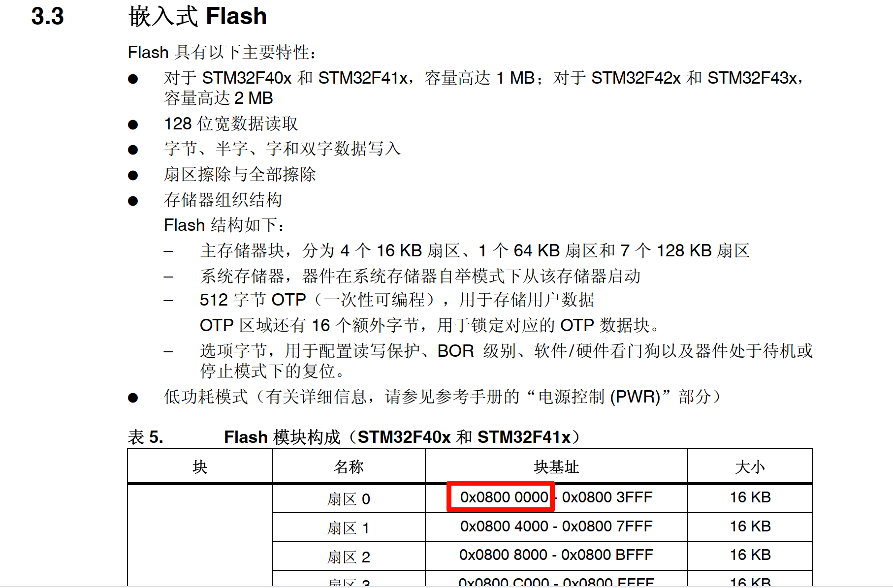
Boot Flow Diagram

On power-up, the CPU fetches the main stack by default from , but depending on the levels of BOOT0 and BOOT1 it can map other addresses onto
- BOOT0 high, BOOT1 high: map onto 0x00000000
- BOOT0 high, BOOT1 low: map onto 0x00000000
Questions
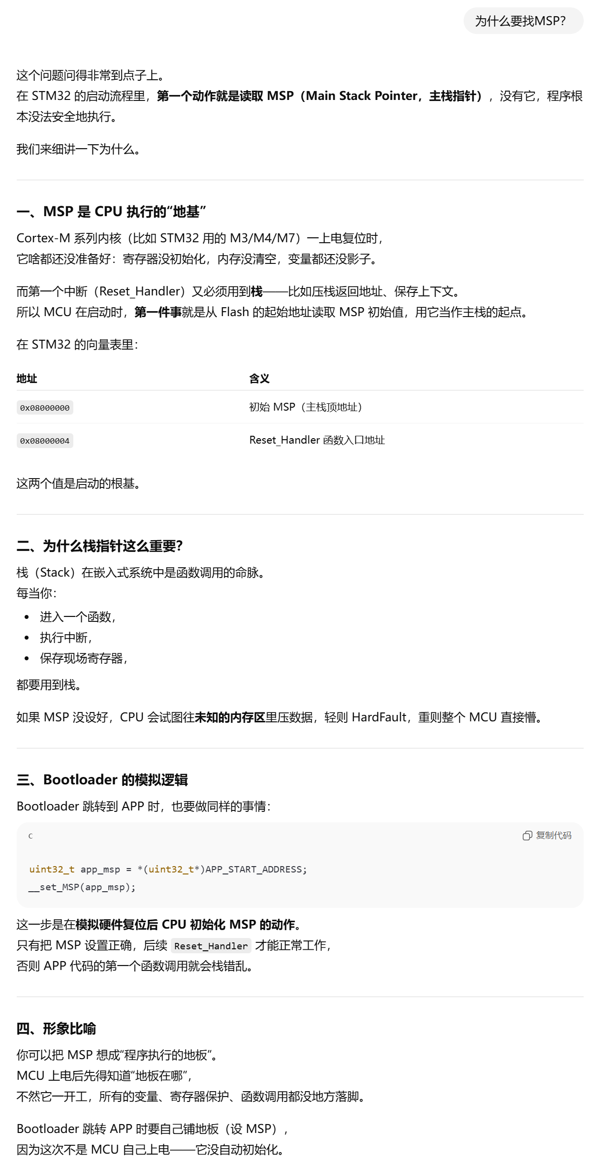
Why Look for the MSP?
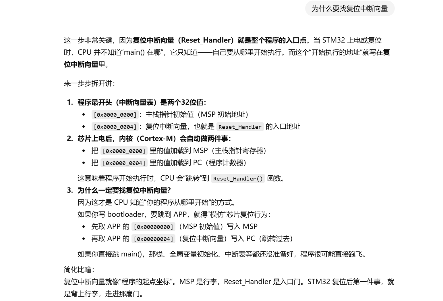
Why Look for the Reset Interrupt Vector?
Why Can the BOOT Pin Levels Determine Where the CPU Looks for the MSP and Reset Interrupt Vector?
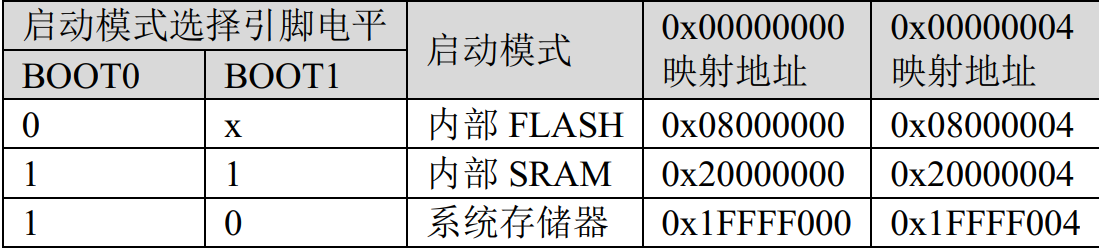
Because after the chip powers up, the CPU first goes to 0x00000000 and 0x00000004 to find the MSP and the address of the reset interrupt vector table;
on power-up the system first checks the BOOT0 and BOOT1 pins, and depending on the pin levels it maps different addresses onto 0x00000000. For example, if BOOT0 is 0, then 0x08000000 is mapped onto 0x00000000, so the CPU goes to flash to find the MSP and the address of the interrupt vector table; if both BOOT0 and BOOT1 are 1, then 0x20000000 is mapped onto 0x00000000, so the CPU goes to sram to find the MSP and the address of the interrupt vector table
A Simple Jump Routine
Optimizing for Size
Using O3 optimization can shrink the boot size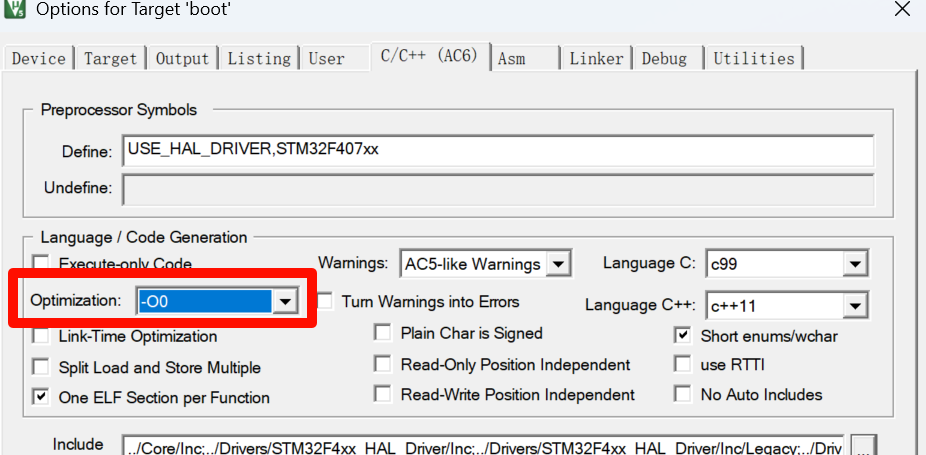
Getting the Binary File
fromelf --bin -o "$L@L.bin" "#L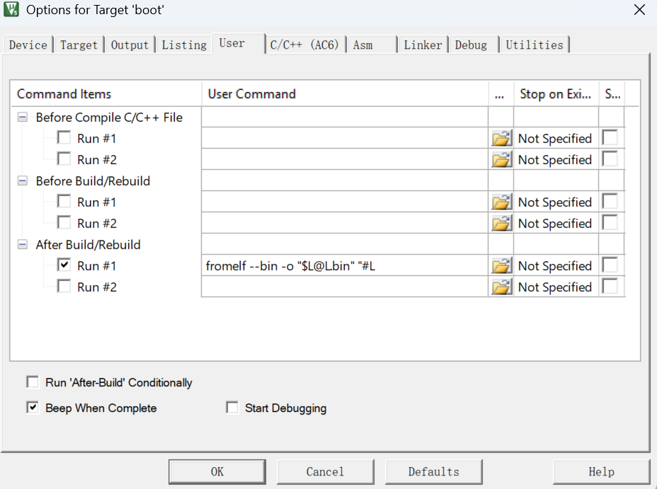
Boot
Create a normal LED-blink program, name it boot, use 0x08000000 as the download location and 0x8000 as the download size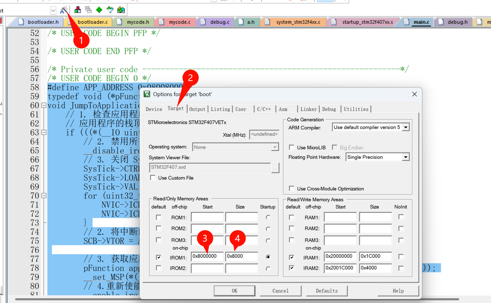
// The app program's location in the chip flash
#define APP_ADDRESS 0x08008000U
typedef void (*pFunction)(void);
void JumpToApplication(void) {
    // 1. Check whether the application address is valid
    // The application's stack top address is located in the first word of its start address
    if (((*(__IO uint32_t*)APP_ADDRESS) & 0x2FFE0000) == 0x20000000) {
		// 2. Disable all interrupts (to prevent Bootloader interrupts from interfering with the App)
        __disable_irq();
        // 3. Turn off SysTick and clear pending interrupts (a clean execution environment)
        SysTick->CTRL = 0;
        SysTick->LOAD = 0;
        SysTick->VAL  = 0;
        for (uint32_t i = 0; i < 8; i++) {
            NVIC->ICER[i] = 0xFFFFFFFF;  // Disable all interrupts
            NVIC->ICPR[i] = 0xFFFFFFFF;  // Clear pending flags
        }
        // 2. Redirect the interrupt vector table to the application address
        SCB->VTOR = APP_ADDRESS;

        // 3. Get the application's stack top address and reset handler address
        pFunction app_reset_handler = (pFunction)(*(__IO uint32_t*)(APP_ADDRESS + 4));
        __set_MSP(*(__IO uint32_t*)APP_ADDRESS);
		// 4. Re-enable interrupts
		__enable_irq();
        // 5. Jump to the application
        app_reset_handler();
    }else{
		// No app detected

	}
}

int main(void)
{
  HAL_Init();
  SystemClock_Config();
  MX_GPIO_Init();
  MX_USART1_UART_Init();
  /* USER CODE BEGIN 2 */
	JumpToApplication();
  /* USER CODE END 2 */
  while (1)
  {
	HAL_Delay(100);
	HAL_GPIO_TogglePin(GPIOB,GPIO_PIN_2);
  }
}
APP
Create a normal LED-blink program to test with, name it app, and change the flash location in the target tab: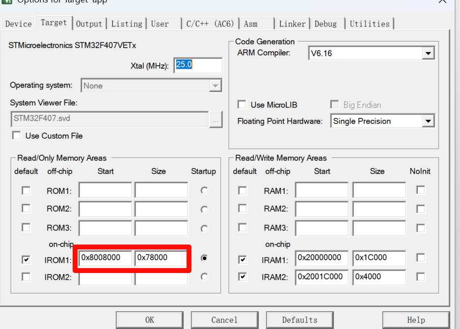
After flashing the app, verify that the app program was downloaded to the specified location as follows: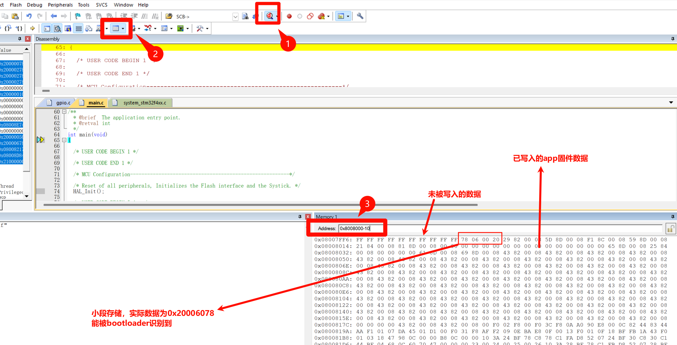
Changelog
0ca31-on