
BootLoader-ESP8266
Overview
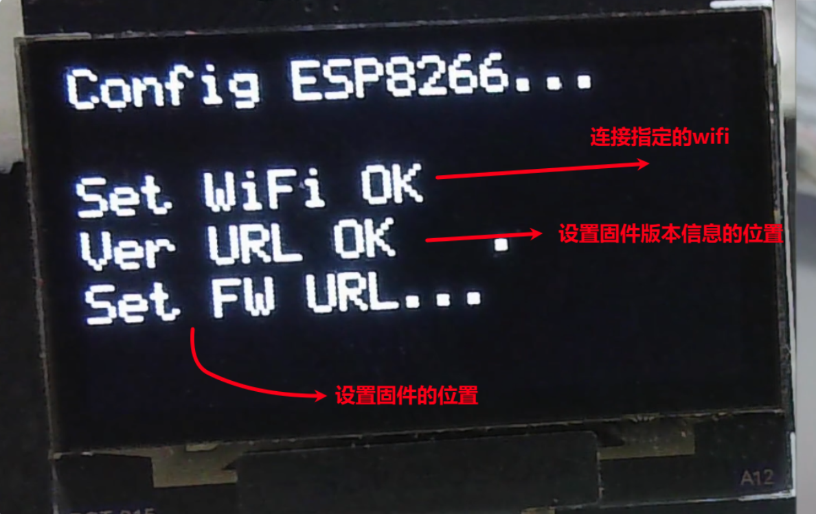
Since it's the STM32 that actively fetches the firmware, I used an AT-command-style architecture to handle connecting to Wi-Fi, setting the firmware location, pulling the firmware, and so on — putting the initiative in the STM32's hands.
No cloud server? No problem — you can just use your own computer as the server.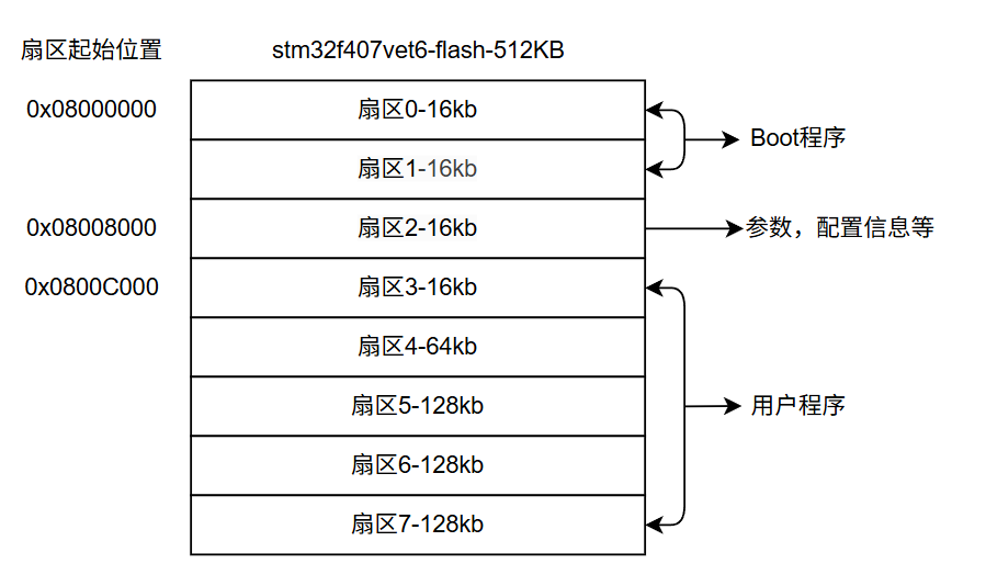
What It Looks Like in the Video


The ESP8266 Side
1. Introduction
This firmware turns the ESP8266 into a Wi-Fi co-processor (gateway) for the STM32. It receives AT commands from the STM32 over the serial port (UART), handles connecting to Wi-Fi, manages configuration data (EEPROM), and downloads firmware data from a specified HTTP server. It then sends that data to the STM32 using a custom packet protocol, enabling OTA (Over-The-Air) updates.
2. Hardware Connection and Communication Parameters
- Communication interface: UART (Serial)
- Baud rate:
115200bps - Wiring:
- ESP8266
TX<--> STM32RX - ESP8266
RX<--> STM32TX - GND <--> GND
- VCC <--> 5V
- ESP8266
3. Boot Sequence and Default Configuration
Once powered up, the ESP8266 does the following:
- Load configuration: Read the EEPROM. On first run (when the magic number check fails), the default configuration is loaded and written to the EEPROM.
- Connect to Wi-Fi: Try to connect to the SSID in the configuration.
- Status output:
- Booting output:
[ESP8266] Booting... - Connection success output:
[WiFi] Connected!plus the IP address. - Connection failure output:
[WiFi] Connect Failed - Ready signal:
READY(the STM32 should start sending commands after it receives this).
- Booting output:
Default Configuration (Factory Reset)
- SSID:
aaa - Password:
aaaaaaaa - Version URL:
http://45.192.110.61/version.txt - Firmware URL:
http://45.192.110.61/app.bin
4. AT Command Set
The STM32 controls the ESP8266 by sending string commands; each command must end with a newline character \n.
4.1 Basic Commands
| Command | Description | Success Response | Failure Response |
|---|---|---|---|
AT | Test the communication link | OK | No response |
4.2 Configuration Commands (automatically saved to EEPROM)
| Command Format | Description | Response | Notes |
|---|---|---|---|
AT+SetWifi=<ssid>,<pwd> | Set the Wi-Fi name and password | OK_RECONNECTING or ERR_PARAM | Disconnects and reconnects immediately after being set |
AT+SetVerUrl=<url> | Set the version file URL | OK or ERR_LEN | Maximum URL length 127 bytes |
AT+SetFwUrl=<url> | Set the firmware file URL | OK or ERR_LEN | Maximum URL length 127 bytes |
AT+GetConfig | Query all current configuration | SSID: ...VerURL: ...FwURL: ...OK | - |
4.3 OTA Feature Commands
| Command | Description | Response Data |
|---|---|---|
AT+GetNewVersion | Fetch the version text from the server | Success: <version string>Failure: ERR <HTTP_CODE> |
AT+GetBinSize | Get the firmware size on the server (bytes) | Success: <byte size>Failure: ERR <HTTP_CODE> |
AT+GetBin | Start the firmware download process | See "Firmware Transfer Protocol" below |
5. Firmware Data Transfer Protocol (the important part)
After the STM32 sends the AT+GetBin command, the ESP8266 enters transparent mode. It downloads the firmware in chunks using the HTTP Range header, and packages the data for the STM32 according to the protocol below.
5.1 Packet Structure
Each packet carries 1024 bytes of payload firmware data (or whatever is left in the final chunk).
| Byte Index | Meaning | Notes |
|---|---|---|
| 0 | Frame header | Fixed to 0xAA |
| 1 | Length low byte | Payload length (Low Byte) |
| 2 | Length high byte | Payload length (High Byte) |
| 3 ... (3+n-1) | Payload data | Firmware binary data (max 1024 bytes) |
| 3+n | CRC low byte | CRC16 Modbus checksum (Low Byte) |
| 3+n+1 | CRC high byte | CRC16 Modbus checksum (High Byte) |
| 3+n+2 | Frame trailer | Fixed to 0x55 |
Total packet length: DataLen + 6 bytes.
5.2 Handshake Flow (Flow Control)
To keep the STM32's flash writes from falling behind the serial receive speed, we use a "send one, ack one" scheme:
- ESP8266 sends: one complete packet (structure as in the table above).
- ESP8266 waits: wait for the STM32 to reply with the string
OK.- Timeout: 3000ms (3 seconds).
- On timeout, the ESP8266 outputs
ERR_TIMEOUTand aborts the transfer.
- STM32 handles it:
- Receive the packet -> verify the CRC -> write to Flash.
- Send
OKover the serial port once done.
- Loop: after receiving
OK, the ESP8266 downloads and sends the next packet.
5.3 End of Transfer
Once all the data has been sent, the ESP8266 sends the string: END
5.4 Error Handling
If a network error or server error occurs during the transfer, the ESP8266 outputs: ERR_HTTP <error code> or ERR_SIZE, and then aborts the transfer.
The STM32 Side
This project implements an OTA (Over-The-Air) update Bootloader based on the STM32F407 (matching the sector definitions in the code) and the ESP8266.
The Bootloader runs at the very front of the MCU startup sequence. It connects to Wi-Fi and checks whether the server has a newer version of the firmware. If it does, it downloads the firmware, writes it to Flash, and finally jumps to the user application (App) to run it.
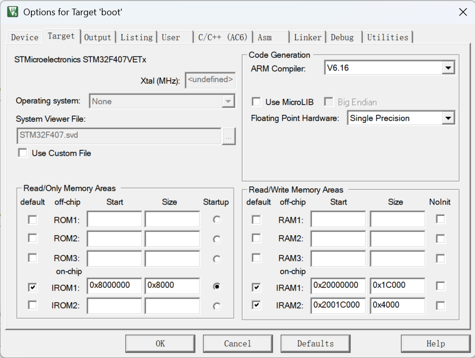
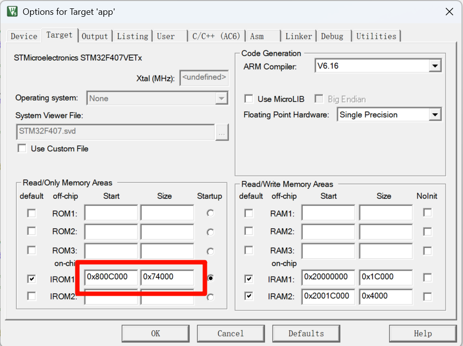
Keil Configuration
| boot keil | app keil |
|---|---|
 |  |
1. Core Features
- Network communication: Control the ESP8266 over serial AT commands to connect to Wi-Fi and the HTTP server.
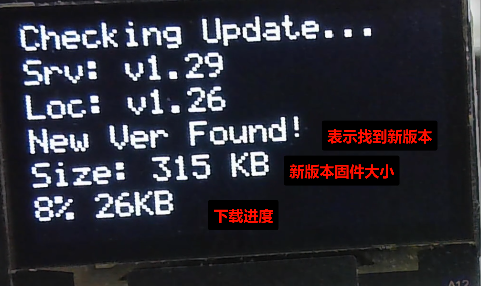
- Version management: Compare the version on the local Flash against the one on the server to decide whether an update is needed.
- Firmware download: Supports HTTP
Rangeresumable (chunked) downloads, and receives data over a custom protocol (with CRC16 verification). - Flash operations: Automatically erase the App region, write the new firmware, and update the version metadata.
- Program jump: Safely jump to the user App to run it.
2. System Memory Layout (Memory Map)
This is the Bootloader's most critical configuration — it determines where in Flash the program lives.
| Region | Start Address | Sector (STM32F4) | Purpose |
|---|---|---|---|
| Bootloader | 0x0800 0000 | Sector 0 ~ 1 | Where this code lives; runs by default when the system powers on. |
| Metadata | 0x0800 8000 | Sector 2 (16KB) | Metadata region. Stores the version number, publisher, and update time. |
| Application | 0x0800 C000 | Sector 3 ~ 7 | User APP region. The downloaded firmware gets written here. |
Note: For the APP you write yourself, the start address in the Keil project must be set to
0x0800C000, and at initialization you must set the interrupt vector table offset withSCB->VTOR = 0x0800C000.
3. Core Data Structures
3.1 AppMetadata_t (version metadata)
Stored in Flash Sector 2, it records the information about the currently installed firmware.
typedef struct {
    uint32_t magic_word; // Valid flag (0xA5A5A5A5), used to determine whether version info has already been written
    char version[32];    // Version string, e.g. "v1.0.2"
    char publisher[32];  // Publisher
    char date[32];       // Release date

} AppMetadata_t;
4. Key Functions in Detail
4.1 Initialization and Configuration
ESP_Config_Init(void)
- What it does: Initialize the ESP8266, set the Wi-Fi credentials and the server URLs.
- Logic:
- Send
ATto check whether the module is online. - Send
AT+SetWifito set the SSID and password. - Send
AT+SetVerUrlandAT+SetFwUrlto set the resource addresses.
- Send
- Teaching point: It uses a simple "send command -> wait for a specific reply" mechanism, which is the most common way for embedded systems to talk to a module.
4.2 Core OTA Logic
OTA_CheckAndDownload(void)
This is the main business logic called from main, and the flow goes like this:
- Get the server version: Send
AT+GetNewVersion. - Compare versions:
- Read the local version at Flash
0x08008000. - If the server version differs from the local one, or there's no local version info (magic word doesn't match), trigger an update.
- Read the local version at Flash
- Get the firmware size: Send
AT+GetBinSize, used to calculate the download progress percentage. - Erase Flash: Call
Flash_Erase_App()to erase Sector 3 through Sector 7, making room for the new firmware. - Download loop:
- Send
AT+GetBinto request data. - Receive protocol packets: header (
0xAA) + length + data + CRC + trailer (0x55). - Verification: Compute the CRC16; if it matches, write to Flash (
Flash_Write_Data) and replyOK; otherwise reply with an error code. - End detection: If the character
ENDis received, the download is complete.
- Send
- Wrap up: Update the metadata (
Flash_Update_Metadata) and restart the MCU.
4.3 Low-Level Hardware Operations
JumpToApplication(void)
- What it does: Jump from the Bootloader to the App. This is the Bootloader's "last mile."
- Key steps:
- Check the stack top address:
if (((*(__IO uint32_t*)APP_ADDRESS) & 0x2FFE0000) == 0x20000000)— makes sure the APP address is valid and the stack pointer is within RAM. - Disable interrupts:
__disable_irq(). An interrupt firing during the jump would cause a HardFault, so interrupts must be disabled globally. - Clean up: Shut down SysTick and clear pending NVIC interrupt bits.
- Redirect the vector table:
SCB->VTOR = APP_ADDRESS. Tells the CPU that the interrupt vector table now sits at the APP's start address, not the Bootloader's. - Set the main stack pointer (MSP):
__set_MSP(...). Restore the stack pointer to the initial state the APP expects. - Jump: Perform a function pointer jump.
Flash_Erase_App(void)
- Check the stack top address:
- What it does: Erase the Flash region holding the App.
- Details: This code is configured to erase 5 consecutive sectors starting at
FLASH_SECTOR_3. On the STM32F4, Flash is erased sector by sector, and you must erase before writing (which flips the bits to 1).
4.4 Helper Utilities
UART_Flush(void)
- What it does: Flush the serial receive buffer.
- Why it matters: Before sending a new command, if the buffer still holds leftover junk from the previous exchange (like
\r\n), subsequent parsing breaks. This function loops over the register until it's empty, keeping communication reliable.crc16_modbus(...) - What it does: Compute a checksum over the data.
- Why it matters: Serial transfers are prone to corruption, and a CRC check guarantees that the data written to Flash is exactly the same as the file on the server — preventing a bricked device.
Changelog
0ca31-on